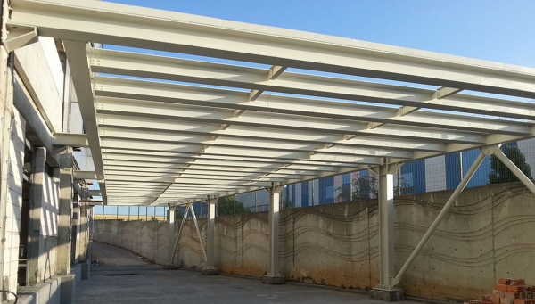
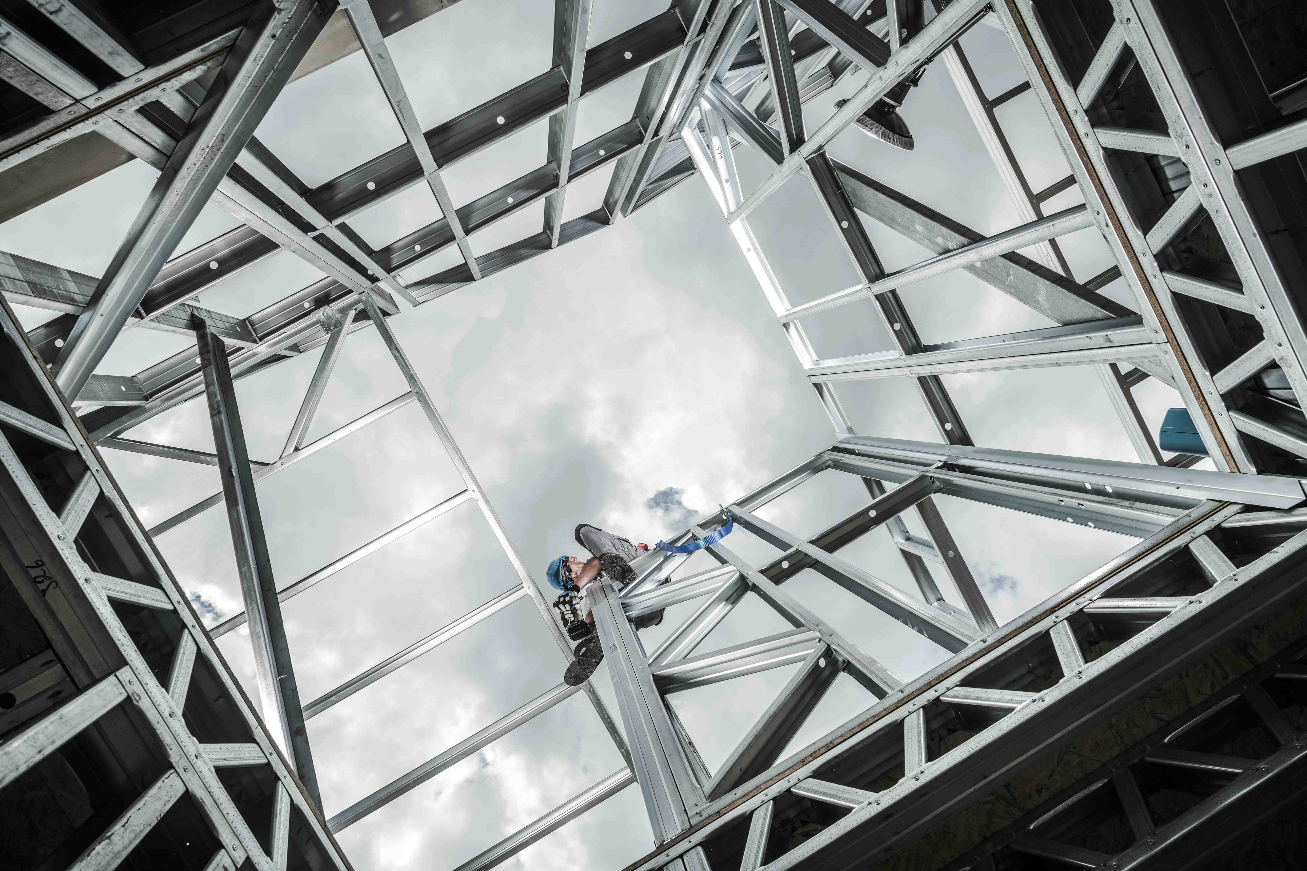
After the assembly of some of the steel columns, the wall cross and frame beams must be assembled with a team from behind. In industrial type single-storey buildings, horizontal loads in the longitudinal direction of the building are generally designed and applied to be transmitted to the foundation using central or eccentric braced shears.
- Column attachments should not be allowed close to the support areas.
- Especially in structures with articulated column-foundation joints, vertical braces or frames must be completed and assembly must be continued.
- When cross-length errors are encountered in the assembly of the wall braces, the connection is tried to be made by ovalizing the holes.
- It should not be allowed to enlarge the holes above the tolerances given by the specifications.
- The transverse direction of the building is formed by roof trusses or full-body frame beams, which together with the columns form the moment frame.
- Moment-transmitting column-beam connections should be given in static calculations and their application should be done in the same way.
- If the column-beam connection is too high and thick butt plates come out in these joints, additional formation with full penetration welded lower and upper headboards should be preferred, since these will require limiting the floor height or the use of the volumes at full storey height. In addition, in such structures, there may be a crane beam level before the roof level, and crane beams with various load carrying capacities, usually in the style of simple beams with a single span, resting on the console located on the columns in the longitudinal direction.
- In order for the roof frame beams or crane beams to be assembled, the wall braces in the longitudinal direction between the columns must also be connected, the shims under the base plate that connect the column anchors to the foundation must be placed and the anchor nuts must be tightened.
- If the assembly is started before these conditions are met, there will be a problem in the assembly of the crane beams in the longitudinal direction and the frame beams in the transverse direction.
- For example, in one application, during the fastening of the roof truss on the columns, the column heads are tied by pulling, since the distance between the columns is shorter than the required project; It has been observed that when vertical loads come on the structure after assembly, the shear force capacity of these connecting bolts has been exceeded, causing the roof to collapse.
- Its columns are connected by crosses; In the sections of the building where the assembly of some roof trusses or frame beams in the transverse direction has been completed, the assembly of purlins and roof braces is started from one end of the structure.
- Purlins can be generally calculated and designed as a 2-span continuous beam, a simple beam as a space purlin or a gerber beam. These should be connected to the roof beams with bolts in accordance with the selected carrier system models.
- As far as possible, roof trusses or beams are in the plane of the upper head, and welded purlin joint should be avoided in order to form a continuous beam; It should be preferred that the continuity joints are made with bolts. Purlins also transfer pressure as perpendiculars of horizontal braces formed on the roof plane under the influence of earthquake or wind loads. For this reason, the details should be calculated and applied in connection with the roof beams, taking this matter into account. In order to prevent lateral buckling in the purlins, care should be taken to keep the buckling lengths in accordance with the specifications by keeping them in the weak direction. The purlins should be connected at 1/3 points with suspension rods to reduce the buckling lengths in the direction of the roof slope.
- Roof braces may not be attached to the roof beams in the upper head plane to the connection plate holes on them, it is desired to enlarge them by making them oval. These should not be allowed. Since the intersection point in the middle of the roof braces does not come under the purlin, the cross attachment cannot be connected to the purlin sub-heading. Somewhere in the two diagonal openings they are interconnected among themselves. In this case, since the limit values given for the transverse buckling length will be exceeded, the cross section will be insufficient. In addition, the vertical displacement limit values are exceeded by the effect of its own self-weight. In this case, an additional element should be placed between the two purlins and the cross joint should be made under this additional element or the cross system should be changed.


